Battery powered Pi and servo switch
May 26, 2013 Leave a comment
This post will outline the details of a couple of circuits I designed and built for my robot. The first is a regulator to supply my Raspberry Pi with power from a 7.2V battery. Although a simple circuit, it has some features that make it very easy to use to power the pi. Below is the schematic for the circuit, designed using Eagle.
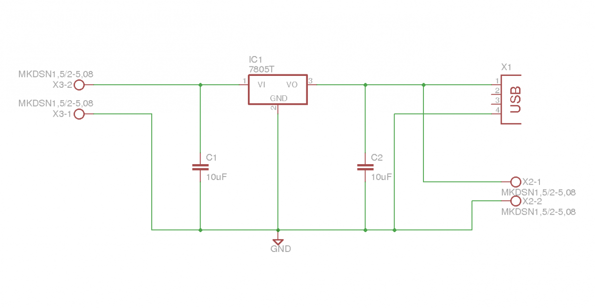
Regulator circuit for Raspberry Pi battery supply
The regulator is a 3A, 5V low drop out regulator (part no MIC29300-5.0WT) even though the schematic shows a different regulator. I realise that using a regulator like this is not the most efficient way of dropping voltage. As the current draw is relatively low (measured at around 0.7-0.8A with everything plugged in and running) and not a huge voltage drop is needed (8V for a fully charged battery dropped to 5V) then this approach is sufficient and quite cost effective. A good heat sink is required for the regulator, which I found out after making the circuit and not leaving enough room for a large heat sink. The regulator has been performing well with just a small heat sink for the moment but gets quite hot. I’m going to see how this goes and maybe redesign the PCB to allow for a bigger heat sink at some point. The feature I included in this design was having the 5V output connected to a USB socket, and also to some screw terminals. This means a standard cable can be used to connect power to the Raspberry Pi’s USB power connector. The screw terminals allow power to also be connected to my USB hub. The picture below shows the circuit built and mounted to my robot.

Regulator built and mounted to robot
The second circuit designed and built for my humanoid robot is a switch to turn the servo supply on and off. Let me explain why this is useful. At the moment, the Raspberry Pi on my robot is running headless and I am using a laptop to connect to the Pi via SSH. I can run my python GUI and control the robot from the laptop. I wanted a way to switch the servo power on when I run the GUI and off again when the program is closed. This will help the batteries last longer by cutting the power when I’m playing around with code and saves my legs walking over to the robot to power up the servos when its time to test said code. Anyway, below is the schematic for the circuit.

Servo switch schematic
The relay used has a 6V coil and I’m using the supply voltage for the servos to switch the relay. A 2N2222 transistor is used to switch voltage to the coil with an output from the Arduino switching the transistor. A resistor to limit current, and another to pull the transistor gate low when the output from the Arduino is low or not present are required. Also a diode across the relay coil is recommended. I have built and tested this circuit and mounted it to the robot. I works great and does exactly what I intended it to do. The picture below shows the circuit in all its glory.

Servo power switch
With the addition of these two circuits and some fully charged batteries, my robot can now roam around untethered. I really need to work on some code now to take advantage of this. Another task on my to-do list is to design and build some optical encoders for the wheels. I’ll be sure to keep you informed of any progress I make.


