I was very pleased with the way BFRMR1 turned out, but it had some design flaws that I needed to address. The servos used for the drive wheels were a bit too slow. The drive wheels were positioned near the centre of the robot to help limit the size of the turning circle, but meant that the robot would tip forwards when stopping. It also meant that I couldn’t mount anything to the front of the robot, such as a gripper. Wheel encoder resolution was also a bit limited. An idea started forming in my mind for a new robot.
The idea was to make a four wheeled robot, with each wheel driven independently. I wanted to stick with using servos to drive the wheels. I love servos. They are cheap and very easy to control. But they can be slow! My idea evolved to making a gearbox to speed the servos up a bit, whilst taking the hit of losing a bit of torque. However, for this new robot it wouldn’t matter too much as I was doubling the number of drive wheels. I thought of several ways of gearing the servos. Drive belt and pulleys was the first option but I decided to go for gears instead. I could have bought the required gears but I thought that this project was as good an excuse as any to invest in a new piece of equipment, a 3D printer!
After a bit of research I decided on a prusa i3 printer bought as a kit. I painted the aluminium frame and after a few days and a couple of long nights I had my printer assembled and working.
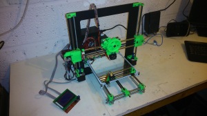
Prusa i3 3d printer
After calibration and a number of test prints, I set about designing some gears to form a gearbox. I used OpenSCAD to design all the parts for the robot. To design the gears I downloaded a gear generator from thingiverse http://www.thingiverse.com/thing:3575. I started with a 25 tooth gear that would be connected directly to a servo horn, then a 14 tooth gear that would be connected to the wheel drive shaft. Attached to the 14 tooth gear is a 45 tooth gear with a finer pitch to drive an encoder disc with a 14 tooth gear attached. All of this together would increase the top speed of the servo and give me an encoder resolution of 180 pulses per wheel revolution. It took a few tries to get each of these gears right and some of the prototypes are shown in the picture below.
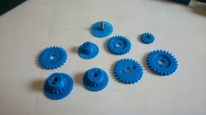
3D printed gear prototypes
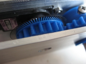
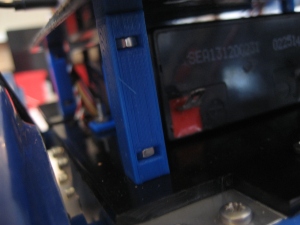
With all of the gears designed I made a trial gearbox. I wanted to use aluminium rectangular box section to house the gearbox. This means all of the gears are hidden and contained and also means that the gearbox could form a part of the robots chassis. The prototype gearbox just used a short section of the aluminium box as a test. The picture below shows the gearbox from the end with the encoder disc nearest the camera.
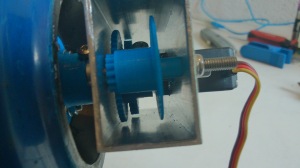
Prototype gearbox
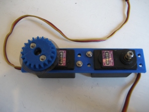
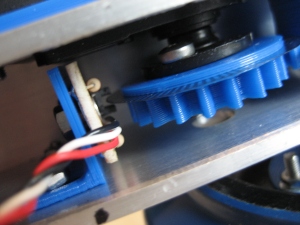
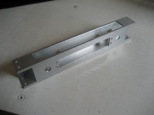
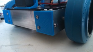
The final gearbox design used a long length of aluminium box section with two servos attached and two gearboxes within. This would form the drive for one side of the robot. Access holes were cut into the box section so allow assembly and adjustment of the gearbox and the picture below shows the view into one of the access holes. You can see the two servos mounted with gears attached and the drive shaft passing through the box section with its gear attached. The encoder discs are hidden.
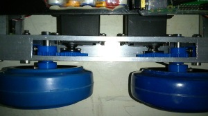
One completed gearbox
I also designed and printed some bushes for the drive shaft to run in that clipped into holes drilled in the aluminium box section. The hole through the middle of these is slightly undersized so that they can be drilled out to exactly the right size for the shaft to fit in.
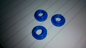
3D printed bushes
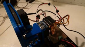
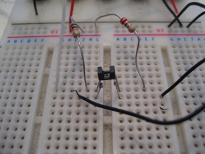
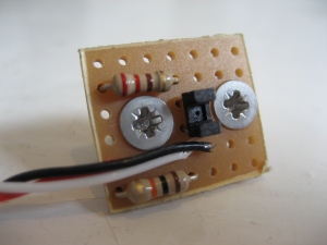
The encoders consists of a 28 slot encoder disc and a photo-interrupter to detect each of the slots as the disc turns. I decided on using sharp GP1A52LRJ00F slotted optical switches. These have photologic outputs so only a minimum of external circuitry is required to interface these with the Arduino. In fact only one resistor is needed so I used stripboard to make four encoder circuits that were then mounted inside the aluminium box section with the encoder discs turning between the sensors.
With two gearbox/chassis sections made I had two sides of the chassis. To join these together and make a complete chassis I needed to design some brackets. These brackets attached aluminium box section cross members to the gearbox sections to make a rectangular chassis. These are shown in the picture below.
Chassis bracket
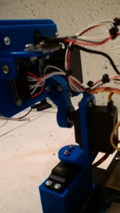
One feature I wanted for this robot was the ability to separate the electronics and sensors from the chassis easily. To achieve this I decided to mount the Arduino mega, the Raspberry Pi, the batteries and the USB hub on a sheet of HDPE plastic that would then be bolted to the chassis with four bolts. Should I need to work on the chassis in the future I could just undo these four bolts, disconnect the encoders and drive servos from the Arduino and remove the electronics board. I also decided to mount the head pan/tilt mechanism to this board as well. The picture below shows the chassis with the electronics board attached.
Assembled chassis and electronics
The head pan/tilt mechanism consists of two regular servos and some 3D printed brackets. The picture below shows the bracket that attaches the pan servo to the electronics board.
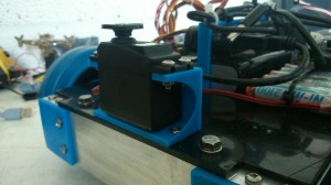
Servo pan bracket
Attached to the pan servo is the tilt servo via another 3D printed bracket. I designed a further piece that fixes to the tilt servo that the head can be bolted to, all shown in the picture below.
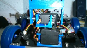
Head tilt servo bracket
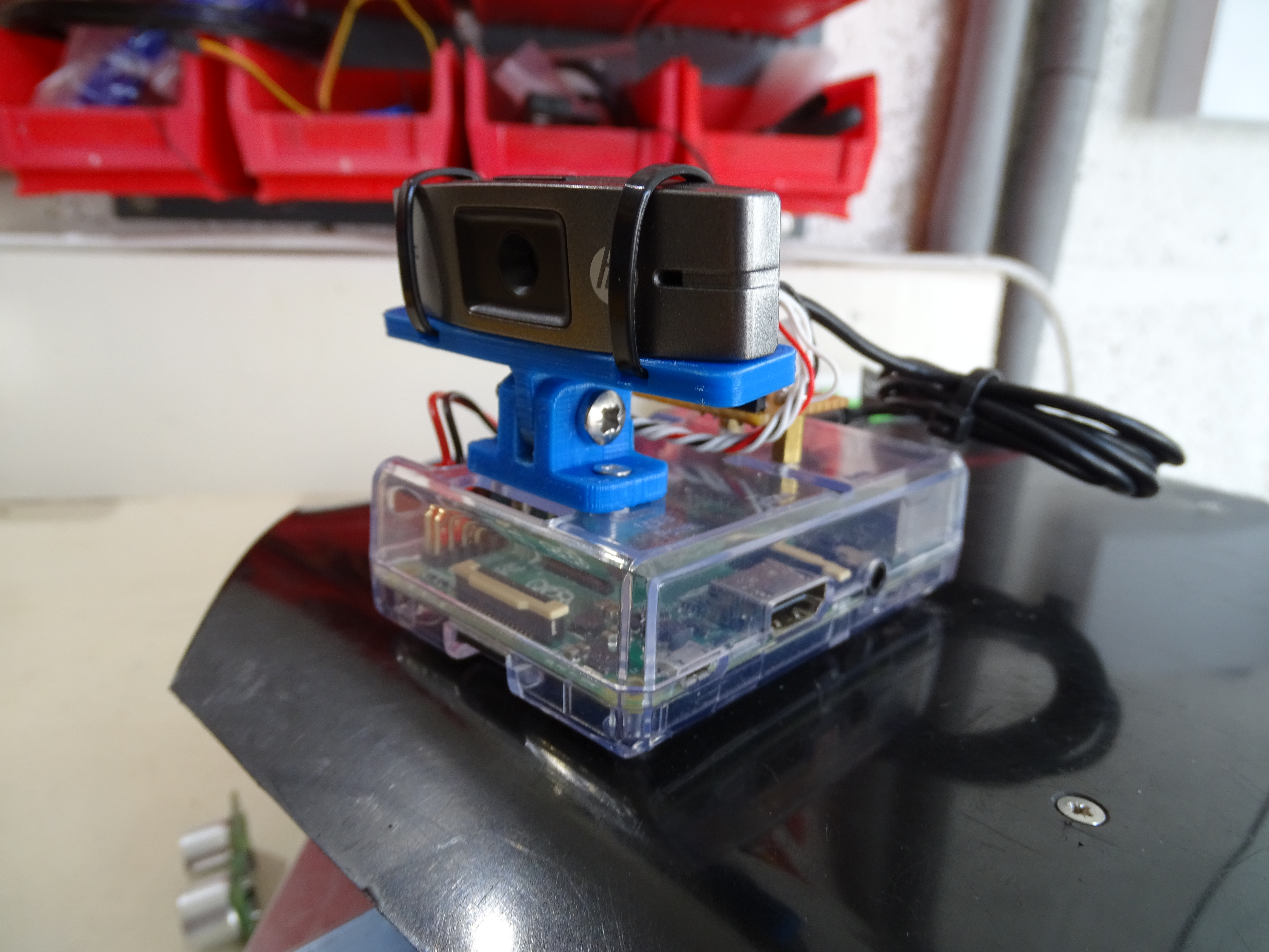
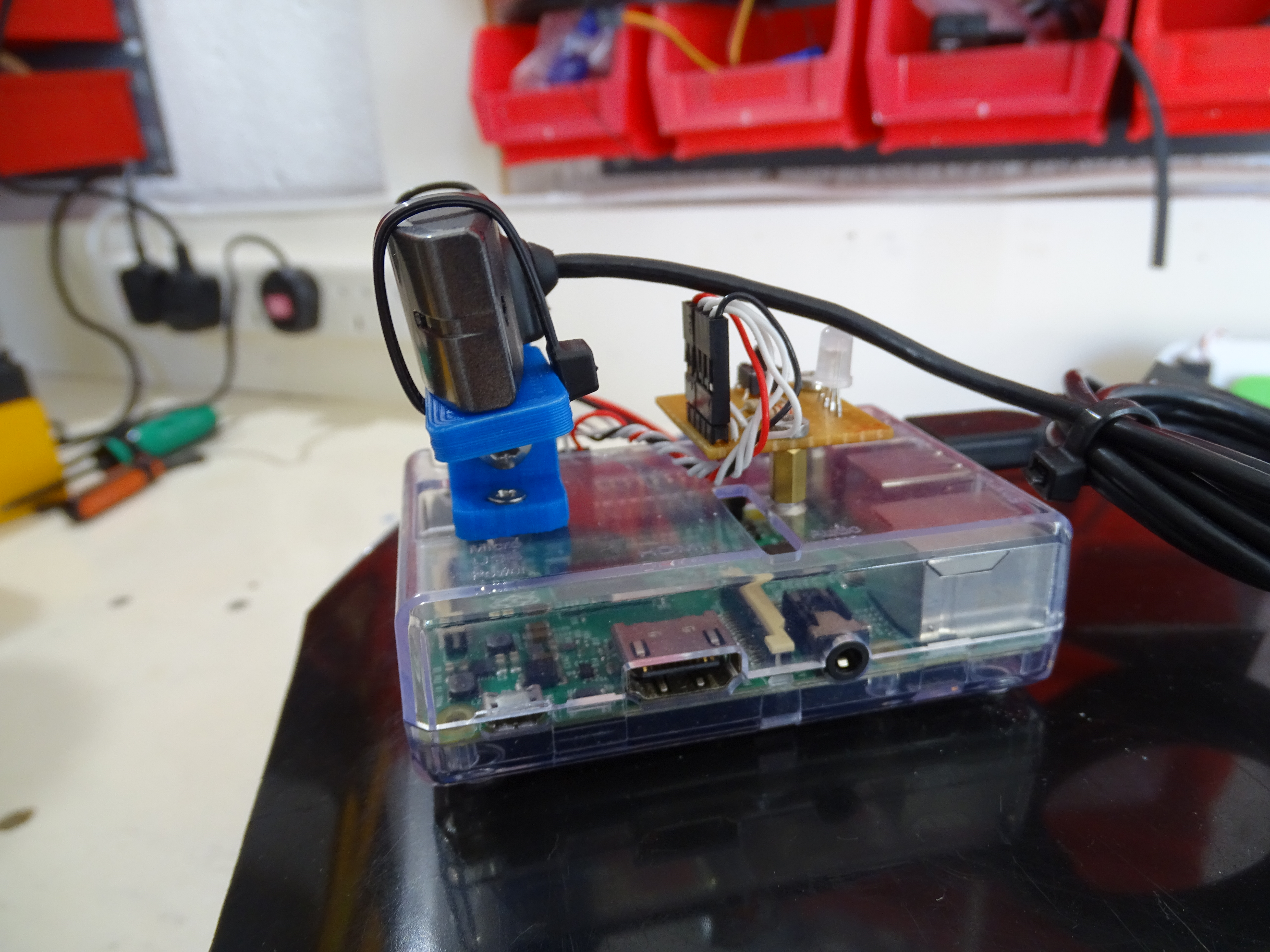
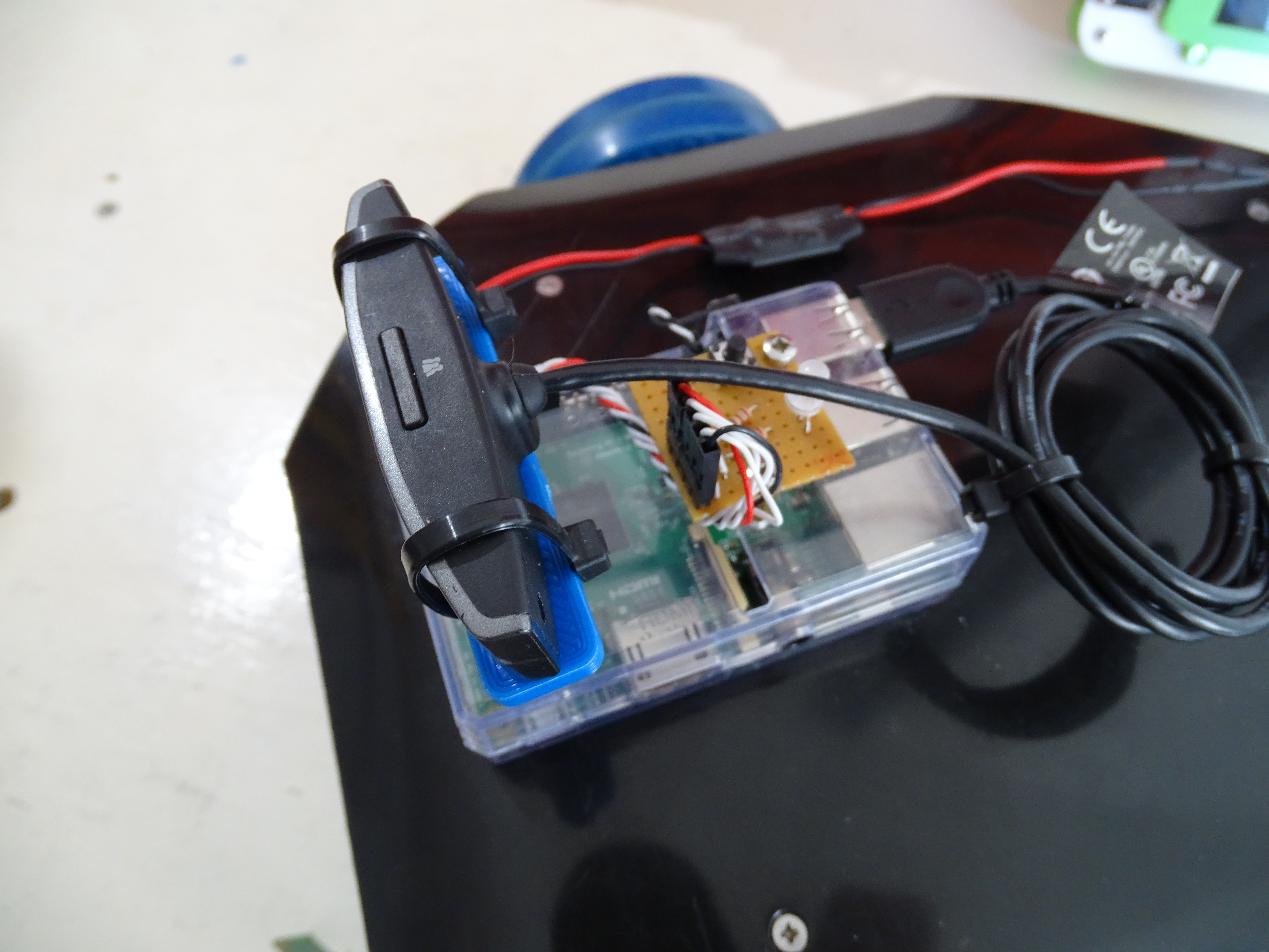
The head of the robot houses a sonar sensor and a webcam. See the picture below showing the assembled head attached to the pan/tilt mechanism.
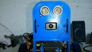
3D printed head
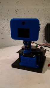
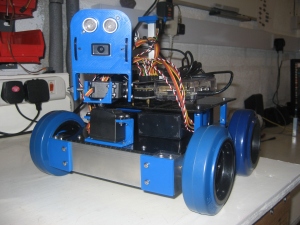
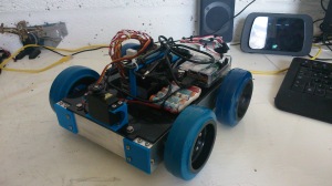
With all of this done the robot is almost mechanically complete. I need to design and print some mounts for two IR sensors that will probably mount to the electronics board either side of the pan/tilt mechanism. The other job to do is to design and print a housing for a small screen and some buttons for controlling the robot without having to connect to it with another PC.
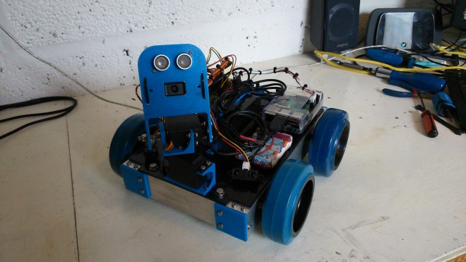
BFR4WD almost complete
I have been developing software for the new robot alongside the mechanical build. I have modified the wheel control loop software from my previous robot to now control 4 wheels at the same time. A lot of the software from the BFRMR1 can be used in this project but one thing that I knew needed work was the communications between the Arduino and the Raspberry Pi. I was using serial communications but I never really liked the protocol I was using, that I developed so I can’t even blame anyone else for it. I am sticking with serial comms but wanted an improved protocol. Inspired by G-code as used on 3D printers I decided to come up with my own protocol to send commands in the form of strings to the robot. I’m calling it BFR-Code for now! The basic idea is that movement commands or requests for data can be sent to the robot along with some data to determine how to move. So a move command string will start with a capital letter M followed by a number to determine the type of move and then any data required proceeded by a capital D. So the command M1 D200 would drive the robot forward 200 encoder ticks. Error codes and data can be returned to the Raspberry Pi in a similar manner. This whole thing is a work in progress and I will make a blog post in the future with full details if this works out well.
For now I am continuing work on the software but I am near to making a video of the robot in action so check in again soon!