BFRMR1 build complete
April 16, 2014 Leave a comment
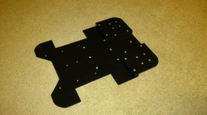
This robot came together very quickly. This was partly due to the fact that I had all the parts I needed already and partly due to this design being a relatively simple one. From my last post to having a robot ready to test took about 3 weeks. Since then I have been modifying software from my humanoid robot for use on a mobile robot. The parts that needed fabricating for my new robot included a base plate to mount everything to, new brackets for the wheel servos and encoders, a bracket for 3 sharp IR sensors, a mounting plate for the Arduino and a new pan/tilt arrangement for the camera and sonar sensor. I wanted to use 40mm castors at the rear of the robot as I have found these to roll really well on carpet. This lead to possibly the trickiest part of the design. I had to raise two sections at the back of the base plate to mount the castors to so that the robot was level and didn’t have a huge ground clearance, which may have made the robot look odd. The picture below shows the finished base plate, painted black.
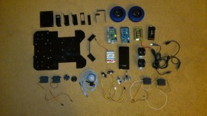
The other brackets and components were fabricated and painted black as well. I decided to modify two servos for use in the head pan/tilt arrangement. I wanted to get a signal from the internal pot to use as feedback of servo position. This involved opening the case of the servo and soldering a wire to the centre pin of the internal potentiometer, which can then be read by the Arduino via an ADC. I knew that this would not be as accurate as using an external potentiometer as I did with my humanoid robot but I was willing to make this sacrifice at this stage to simplify the mechanical design of the pan/tilt arrangement. With all the parts ready for assembly I took a picture of all the components laid out because I’m sad like that and I think it’s cool!
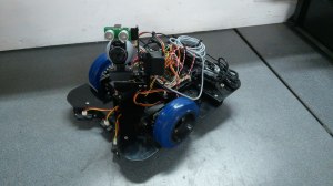
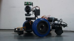
The next task was to assemble the robot. I also needed to make and attach encoder disks to the wheels. These were designed on the computer, printed onto card and glued to the wheels. The assembled robot is shown below.
I still plan to make, or have made, a cover for the robot to hide and contain all the wires and electrical components. This is a work in progress but testing and software development can still continue on the robot as it is.
At the moment I am still testing and modifying software to display data from the robot on a screen and control the robot manually from either a PC or the Raspberry Pi. My goal with this robot is to have several modes of operation that can be selected between. For example; obstacle avoidance, wall following, colour tracking etc. This is very much a work in progress but when I have something working I will make and post a video. That’s it for now, back to software!


