Work was progressing with BFR4WD and I was experimenting with software for object/landmark recognition as well as developing BFR-Code for controlling the robot. However, I started having problems with the old NI-MH battery pack I was using to power the servos. It wasn’t holding its charge for long and the servos were constantly struggling to move the robot. This battery pack had sometimes struggled to deliver the current required when all the wheel servos were working hard when it was working well. I decided it was time for a new battery. This led to a succession of design revisions and many parts of BFR4WD have been redesigned and rebuilt.
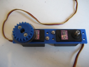
Lets start with the choice of a new battery. I looked into the various options available and settled on a 6V SLA battery to power all the servos. SLA batteries are cheap, easy to charge and able to supply a lot of current if required. The downside is that they are heavy! During the original design of BFR4WD I made the decision to gear the servos to increase the top speed of the robot at the expense of torque to the wheels. This was fine using the previous battery but the additional weight of the SLA battery means this gear ratio would no longer be suitable. I decided to redesign the drive train for each wheel so that the required torque could be delivered. This meant designing some more 3D printed gears with a ratio that increased torque at the expense of speed. I ended up with a 20 tooth gear attached to the servo and a 24 tooth gear on the wheel axle.
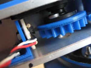
I used this redesign as an opportunity to review the design of the wheel encoders as well. Whilst the previous design worked well, the encoders were mounted in a place the meant most of the robot had to be dismantled in order to adjust, repair or replace them. Looking into various options I settled on sticking with an optical encoder but instead of a slotted disk I would use a printed pattern. This design involves printing the encoder disk pattern onto transparency film using a laser printer. A slotted opto-interrupter looks at this disk and switches depending on whether a printed line is present or not. The final design ended up with the patterned disk attached to the servo gear meaning I could also do away with the third gear/slotted disk of the previous design. This has the advantages of fewer parts to print, fewer holes to drill and fewer moving parts. This all adds up to a simpler design which is lighter and runs more quietly. The picture below shows an encoder disk mounted to the servo gear.
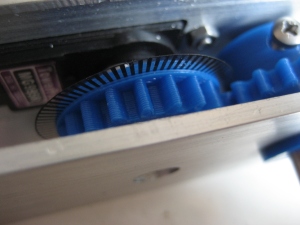
Encoder disk
With the alterations to the gear ratio and the new design for the encoders I was also able to increase the encoder resolution from 180 pulses per revolution to 218.
A redesign of the encoder circuit was also required and I decided to use Sharp GP1S093HCZ0F opto-interrupters. These devices are very small and allow a very compact encoder to be built. A test on a breadboard allowed me to find the correct resistor values to use (10K and 220 Ohm) and test that the device could read the encoder disks as required. The pictures below show the breadboard version and the final encoder circuit which was built on stripboard.
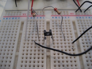
Encoder circuit on breadboard
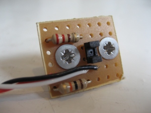
Encoder circuit
To allow the new design drive train to fit in the aluminium box section I’m using to house it, I had to space the servos off from the box section by 3mm. I designed and printed a spacer that would hold both of the servos required for one side of the robot chassis.
Servo Spacer
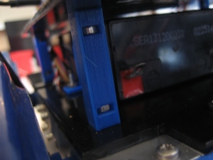
A 3D printed bracket was designed that would mount the encoder circuits in the correct position and allow for some adjustment. These encoders are mounted in the centre of the chassis rail as opposed to the ends as in the previous design. This configuration makes them a lot easier to adjust. Shown below is the finished encoder arrangement mounted in the chassis.
Mounted encoder
This encoder design and gear configuration also meant that I could reduce the overall size of the robot. This design is now 40mm shorter in length but 10mm wider. This has the advantage of setting the wheels closer together along the length of the robot but spacing them further apart across the width of the robot. This helps when the robot is turning on the spot.
I had to fabricate all new chassis parts to fit the new design, one of which is shown below.
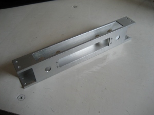
Chassis rail
The picture below shows one of the chassis rails with the servos, gears and encoders mounted. I reused the end joining pieces from the previous design. I also changed the bushes that the axles run in from a push fit design to ones that glue into place.
Due to reducing the overall size of the robot and the addition of a larger battery, space on the chassis to mount everything had decreased significantly. I was forced to start building upwards! I designed some 3D printed stand-offs that would allow me to mount another sheet of HDPE above the first, as shown below.
3D printed stand-offs
This meant that the two batteries could sit on the bottom layer which allowed good access to the connect / disconnect power to them. The Raspberry Pi, Arduino and USB hub could go on the top layer, again giving good access to connect to them. I also added a compass module to the robot. A CMPS03 that I have had lying around for a long time. I designed and printed a mount for the compass and used a length of aluminium box section to raise the compass into the air. My experience is the further the compass is from any other components the better as it reduces interference.
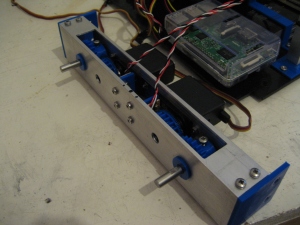
The picture below shows the completed robot. So many things have changed with this redesign I think this will have to be referred to as BFR4WD MK 2. Initial testing confirms that I have much more torque at the wheels due to the change in gear ratio and better current delivering capacity of the battery. The encoders are working perfectly and I have increased resolution meaning more accurate positioning and speed control. The compass works and will be used for navigation. I am very keen to try some more map building using a mobile robot with the addition of data from visual images.
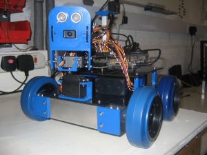
BFR4WD – MK2
