Arduino shield and tidier wires

If you have read some of my previous posts you will know that the state of the wiring on my robot has been causing me distress. It’s not that the wiring was causing issues as such, it’s just that I knew there was a better way of doing it. My design had the Arduino board mounted on the base with many wires connecting it to an interface board mounted on the rear of the robots torso. The better way to do it would be to use a shield that connects to, and sits on top of, the Arduino and mount the Arduino to the rear of the robot torso. So I set about designing and building a shield to meet my needs.

I started with a template made by someone else, no use re-inventing the wheel. I used the one found here http://circuitfun.wordpress.com/2012/01/02/arduino-mega-shield-template-in-eagle-improved/, which I must say is very good!  I then added parts to meet my requirements. I added connectors for all of the servos, connected to the PWM pins. I also added connectors from the ADC pins to interface the potentiometers, with a few spare should I wish to connect anything else at a later date. Connectors from a few digital pins allow sonar sensors to be connected as well as the hand switches. As a bonus I added the servo power switch circuit to the shield so I could do away with the small separate circuit that was performing this task. I then completed the board layout and fabricated the board.

Having completed the board and tested it I would say it was a worth while project. I have got rid of a load of wires from the rear of the robot and cleared some space on the base of the robot. I did have the batteries slung beneath the base which I didn’t like, so these have moved to the top of the base. All in all, this set-up is much tidier and this makes me happy. The picture below shows the Arduino and shield in situ.
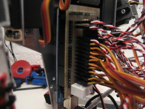
Arduino and shield mounted to the rear of the robot torso

Arduino and shield mounted to the rear of the robot torso

Encoders

I have been doing some testing on my robot, in particular the wheels. I noticed, as expected, that the wheels do not turn at the same speed even when given the same command. This is a common problem and means that the robot does not drive in a straight line. The problem is even more evident when the robot is driving on carpet, as the rear castor takes a while to straighten up, meaning the robot drives on a curved trajectory. The solution to this issue is to add wheel encoders.  I have designed and built encoders in the past so I had a pretty good idea of what was required. I once designed an encoder that fits inside a servo housing, replacing the original electronics. The servos motor could be driven via a motor controller, as you would a normal motor, and the encoder would give feedback of the speed, allowing closed loop control. This design used an infra-red reflective sensor shining onto one of the gears inside the servo which had alternating black and white stripes painted onto it. When combined with a schmitt trigger, this set-up gave a series of pulses, the frequency of which was proportional to the speed of the motor. I didn’t want to use this exact design on my humanoid robot. I didn’t want to modify the servo to run as a normal motor as more hardware would be needed in the form of a motor controller. I decided to use a variation of the design but with the encoder external of the servo, shining onto the wheel itself.  The resolution of the encoder would not be as good doing it this way but it was a sacrifice I was willing to make.

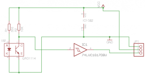
I decided to use the QRD1114 sensor. This is a popular sensor and is used for line following robots quite a lot. It can detect the difference between black and white surfaces, due to the way the IR light reflects or is absorbed by the surface. I wanted to incorporate a schmitt trigger into the design to ensure the output of the encoder is a clean, square wave. I have designed and build these in the past using a comparator and a bunch of resistors. However, after some research I found a buffer chip that will do the job without any external components. The part number is SN74LVC1G17DBVR. It’s a tiny, surface mount chip, perfect for the job. The circuit schematic for the encoder is shown below.

Encoder schematic

Encoder schematic

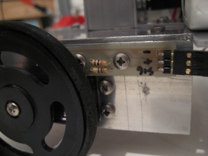
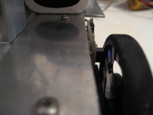
I designed the board for the encoders and fabricated them. For the wheel I needed a disk with alternate black and white stripes printed onto it. I designed the pattern, using  Inkscape and printed it on a laser printer. I cut out the design and glued it to the wheel. I mounted the encoder so that the IR sensor was shining onto the striped pattern. I cut slotted holes to mount the encoder to allow for adjustment. The pictures below show the encoder mounted on the robot.

Side view of encoder mounted to robot

Side view of encoder mounted to robot

Encoder aligned with the wheel

Encoder aligned with the wheel

This set-up gives around 40 pulses per revolution of the wheel. I have connected the signal from the encoders to an external interrupt on the Arduino and set it up so that an interrupt occurs on a change of state. This means the count is incremented every time the encoders sees a change from black to white or vice versa.

I am happy with these encoders. The resolution is not brilliant but is more than sufficient to keep the robot driving in a straight line. I have written a control loop for each wheel, just proportional control at the moment, to keep the wheels spinning at a constant speed.

excitingtechnology.net

Facts and Thoughts on Technological Progress

Turing's Radiator

Diffucult Problems in Futurism

Mind the Leap

One small step for the brain. One giant leap for the mind.

Steve Grand's Blog

Artificial Life in real life

jimsickstee

Hi, I'm Jim. Read what I write and I'll write more to read.